
You are here:
About Entity Relationship Diagram Notation
An entity relationship diagram (ERD), also known as an entity relationship model, is a graphical representation of an information system that depicts the relationships among people, objects, places, concepts, and events in that system.
An ERD is a logical model that is not necessarily reflective of the precise underlying physical data model. However, the Industries ERDs indicate the underlying physical objects by API Name where possible.
Barker Notation
Barker's notation refers to the ERD notation developed by Richard Barker, Ian Palmer, Harry Ellis et al. The notation has features that represent the properties of relationships including cardinality and optionality (the crow's foot and dashing of lines), exclusion (the exclusion arc), recursion (looping structures) and use of abstraction (nested boxes). The notation also features layout conventions that, when followed, assist in the readability of the diagrams and can assist the designer in discovering commonalities between entities that may not have been apparent before creating the diagram.
Entities
An entity is a thing or object of significance, whether real or imagined, about which information needs to be known or held.
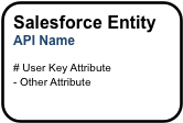
Entities are represented in the diagrams as boxes with rounded corners. Each entity box typically provides two labels (where applicable).
-
The first label is the logical name of the entity (e.g. “Salesforce Entity” in the above). This may correspond to the singular label of the underlying object, but will not always.
-
The second label is the “physical” API Name of the object in your Salesforce org (“API Name” in the above). For Vlocity objects, the API name listed in the diagram omits the managed package namespace (“vlocity_ins__” for example).
Entity boxes may also list one or more attributes that are representative of the attributes of that entity. An attribute is either preceded by a “#” or a “-” character.
-
A “#” indicates an attribute that is part of the logical unique key of the entity. In the above diagram, “User Key Attribute” is considered the user primary key of the entity.
-
A “-” indicates a non-key attribute.
Entity Color Coding
A white box with a black border denotes a standard Salesforce object that Vlocity has not extended.
A light-blue box with a black border denotes a standard Salesforce object extended by Vlocity. Vlocity extensions include custom fields, relationships, and record types.
A blue box with a dark blue border denotes a Vlocity standard object. Vlocity standard objects are delivered as Salesforce custom objects in the Vlocity managed package. The API name shown on these entities are suffixed by the appropriate naming convention for the type of Salesforce custom object used: “__c” for regular custom objects and custom settings, “__mdt” for custom metadata, “__x” for external objects.
A gray box with a dark gray border denotes a possible future Vlocity standard object. These entities have not yet been delivered in a managed package release.
Entities with no borders are virtual. When used in a diagram, these boxes acknowledge the existence of the entity in the logical model for the industry, but the entity is not implemented as a physical object in Salesforce or the Vlocity managed package. The data for this entity is expected to be accessed via external API calls or Salesforce Connect in the deployed solution.
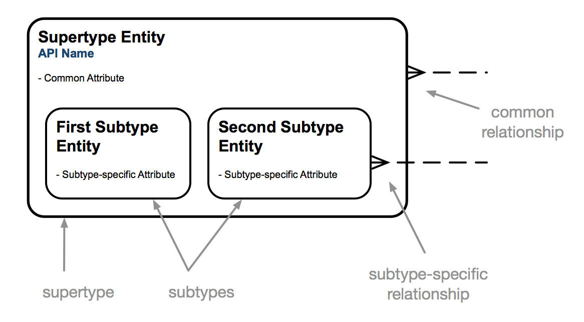
Supertype and Subtype Entities
A subtype of an entity is the definition of a subset of its occurrences. When a set of subtypes is added within a supertype entity, the supertype entity identifies common attributes and relationships while the subtype entities define attributes and relationships specific to each subtype. In the diagram notation, subtypes are mutually exclusive, meaning that any given occurrence must fall into a single subtype. Subtypes can have nested subtypes that further differentiate the occurrences. Subtypes in the diagrams are logical. They may correspond to Record Types provided by Vlocity, but not necessarily.
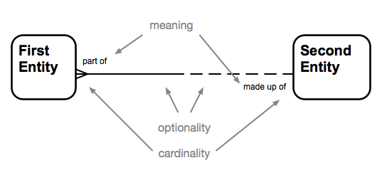
Relationships
A relationship is a named, significant association between two entities.
The notation describes the cardinality, optionality, and meaning of the relationship.
Relationship Cardinality
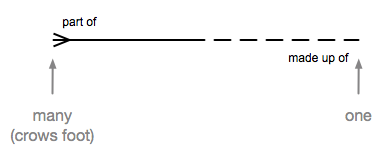
Cardinality indicates the relative numbers of occurrences on each side of the relationship. In the notation, the ends of a relationship line indicate the cardinality of the relationship on that end. A crow's foot on an end indicates that many entity occurrences on that end can relate to a single entity occurrence on the opposite end. The lack of a crow's foot on an end indicates that at most one entity occurrence on that end can relate to a given occurrence on the other end.
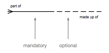
Relationship Optionality
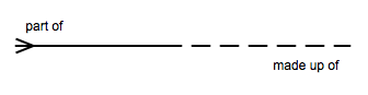
Optionality indicates whether the relationship is required or not for an occurrence on each end. The notation illustrates the optionality of each end of a relationship by showing the relationship line solid or dashed. A solid line indicates that the relationship is required for the occurrence on that end. A dashed line indicates that the relationship is optional. A required relationship is considered stronger than an optional one. The solid line of a required relationship visually reinforces the increased strength of that relationship.
In logical ERDs, the optionality of a relationship may be shown as required even though the underlying physical relationship in Salesforce is optional. For example, the AccountId field on Contact is physically an optional relationship, but if you ignore Private Contacts, the direct relationship of a Contact to an Account is logically required.
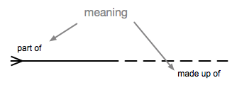
Relationship Meaning
Beyond cardinality and optionality, each relationship between two entities expresses a certain meaning that distinguishes that relationship from other relationships between the same two entities. Relationship end names, such as “part of” and “made up of” in the diagram above, define the nature of the relationship.
When you put the cardinality, optionality and end names of a relationship together, they can be used to form a sentence that describes the relationship.
From left to right: Each <first entity> (may/must) be <end name 1> (one and only one / one or more) <second entity>.
From right to left: Each <second entity> (may/must) be <end name 2> (one and only one / one or more) <first entity>.
For example,
From left to right: “Each Contact must be primarily a contact for one and only one Account.”
From right to left: “Each Account may be primarily represented by one or more Contacts.”
Relationship Color Coding
Relationship lines are color-coded. Black lines are used for relationships provided by Salesforce. Blue lines are used for relationships provided by Vlocity. Gray lines are used for possible future relationships that have not yet been delivered in a managed package release.
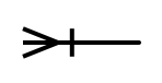
User Key Relationships
Logically, a bar across the crow's foot end of a relationship means that the relationship participates in the user primary key of the entity on that side. A user key relationship is usually, but not always, required. A required user key relationship is arguably the strongest of relationships. It often indicates containment of the child data within a parent entity such as line items in an order. In the Vlocity ERDs, the bar across the relationship line usually, but not always, also indicates that the relationship is implemented as a master-detail relationship in the physical object model. Check the Object Manager in your Salesforce org to determine the data type of the corresponding relationship field.
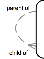
Recursive Relationships
Relationships can be between two occurrences of the same entity. This is called a recursive relationship. A curved relationship line is used to denote recursive relationships.
Mutually Exclusive Relationships
The Barker notation leaves most business rules off of the diagrams in order to focus on the structure of the data model, but a mutually exclusive relationship is one business rule that is informative to the structure so it is noted. A mutually exclusive relationship indicates that only one of the several relationships included in the arc will be used for any given occurrence. Note that two, three, or more relationships can participate in the same mutually exclusive relationship.
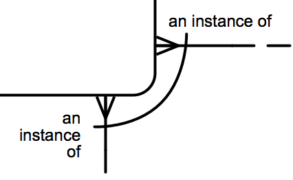
A sentence that describes the above mutually exclusive relationship could be: “Each Entity may be an instance of one and only one First Other Entity or one and only one Second Other Entity.”
In the Vlocity ERDs, a relationship that passes through a gap in the arc is not a part of the mutually exclusive relationship.
Layout Conventions
The Barker Notation also specifies layout conventions that vastly improve the readability of ERDs. These layout conventions recommend the following:
-
Relationship lines should always be straight. No bends in relationship lines.
-
Relationship lines should be drawn up and down or horizontal (left and right). In rare occasions where this is not possible, use a straight line on a diagonal.
-
In order to keep relationship lines straight, entity boxes are resized taller or wider to provide a landing place for the relationships between the two entities.
-
The crow’s feet on relationships should be on the left-side or top-side of the relationship line.
The combination of these layout conventions results in a clean and easy to read diagram. The more important entities (which have more relationships landing on them) are shown larger on the diagram reinforcing their importance. The crow’s foot convention results in similar entities landing in the same area of the diagram which is helpful for understanding the entities. That does result in diagrams appearing upside-down with child entities falling above or to the left of parent entities. However, this ensures that the most specific entities in the diagram fall in the top-left corner of the diagram which makes the diagrams easily recognizable. (Flipping the crow’s foot convention would result in the same common entities falling in the top left of every diagram.)
For More Information
For more information on the Barker notation and entity relationship modeling, see:
-
Richard Barker (1990). CASE Method: Entity Relationship Modelling. Reading, MA: Addison-Wesley Professional. ISBN 0-201-41696-4
-
David C. Hay (1996). Data Model Patterns: Conventions of Thought. New York, NY: Dorset House Publishing. ISBN: 0-932633-29-3